
Manual / Setup
Setup Wizard
The Setup Wizard calibrates the camera in four steps: Video Source, Lens, Camera Calibration and Review. Open it with Open Setup Wizard on the General or Camera & Grid tab. Each step can be revisited from the step bar; Back and Next move between them.
Which way through the Lens step and which calibration mode suit your stage, and what to bring, is in Camera Calibration → Which path to take.
Video Source
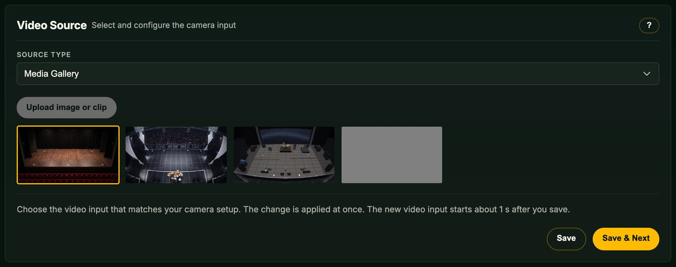
Choose the Source Type of the camera the operator steers markers with and fill in its connection fields, as described in Video Inputs. Save applies the source; Save & Next applies it and moves on. The new video input starts about 1 s after saving. All later steps use a snapshot of it.
For bench testing without a camera, choose Media Gallery and pick the Stage scene.
Lens
Wide lenses make straight lines look curved. This step measures how much, so the overlay curves the same way. Do it once per camera and lens, and again after a zoom change. A camera without visible barrel distortion needs no measurement.
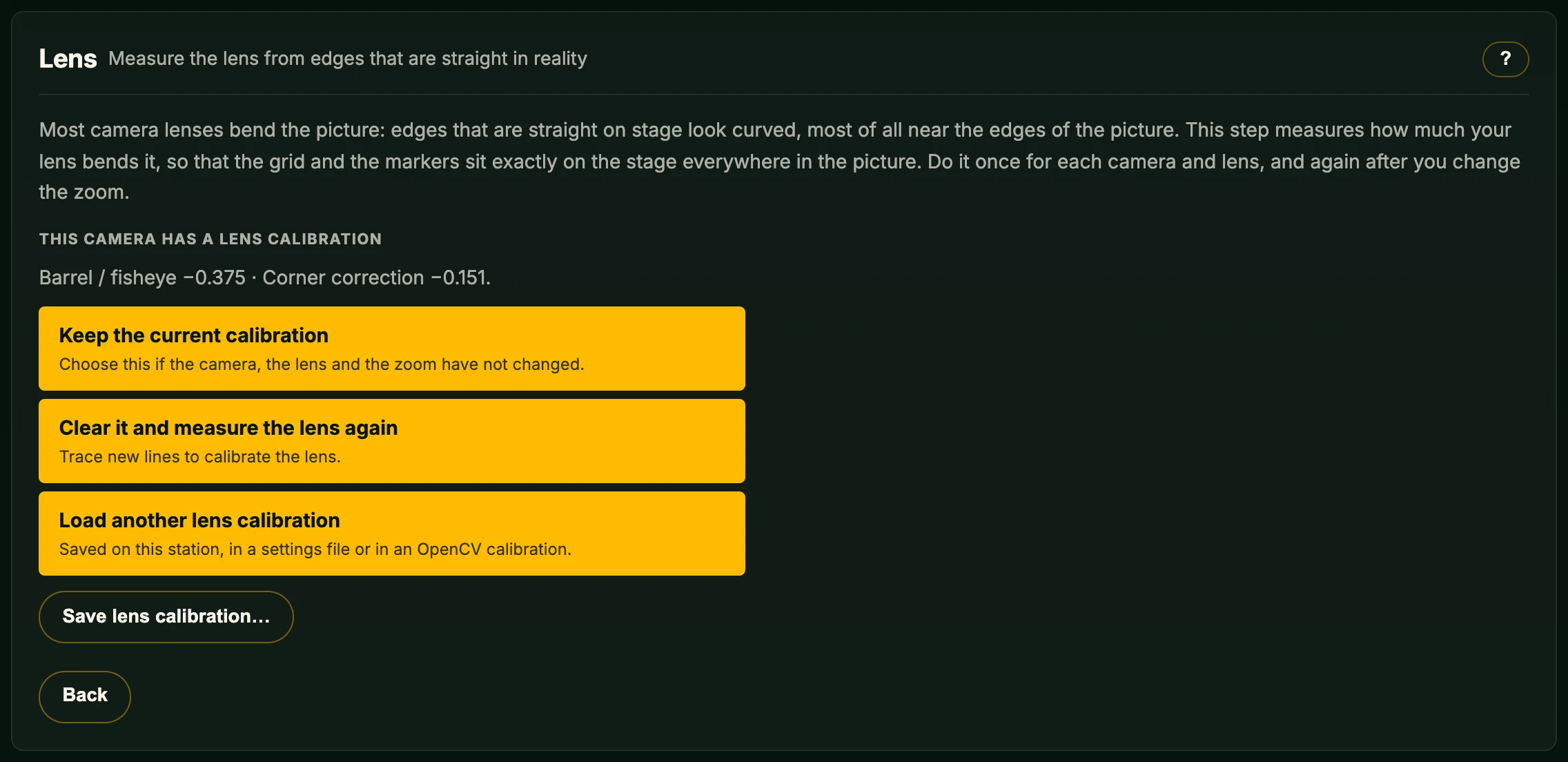
If the camera already has a lens calibration, the step first offers:
- Keep the current calibration
- Clear it and measure the lens again
- Load another lens calibration
- Save lens calibration… – stores the current calibration on this station under a name.
Keep it when the camera, the lens and the zoom are unchanged; clear it when any of them changed or the picture is now a different camera's.
Drawing lines
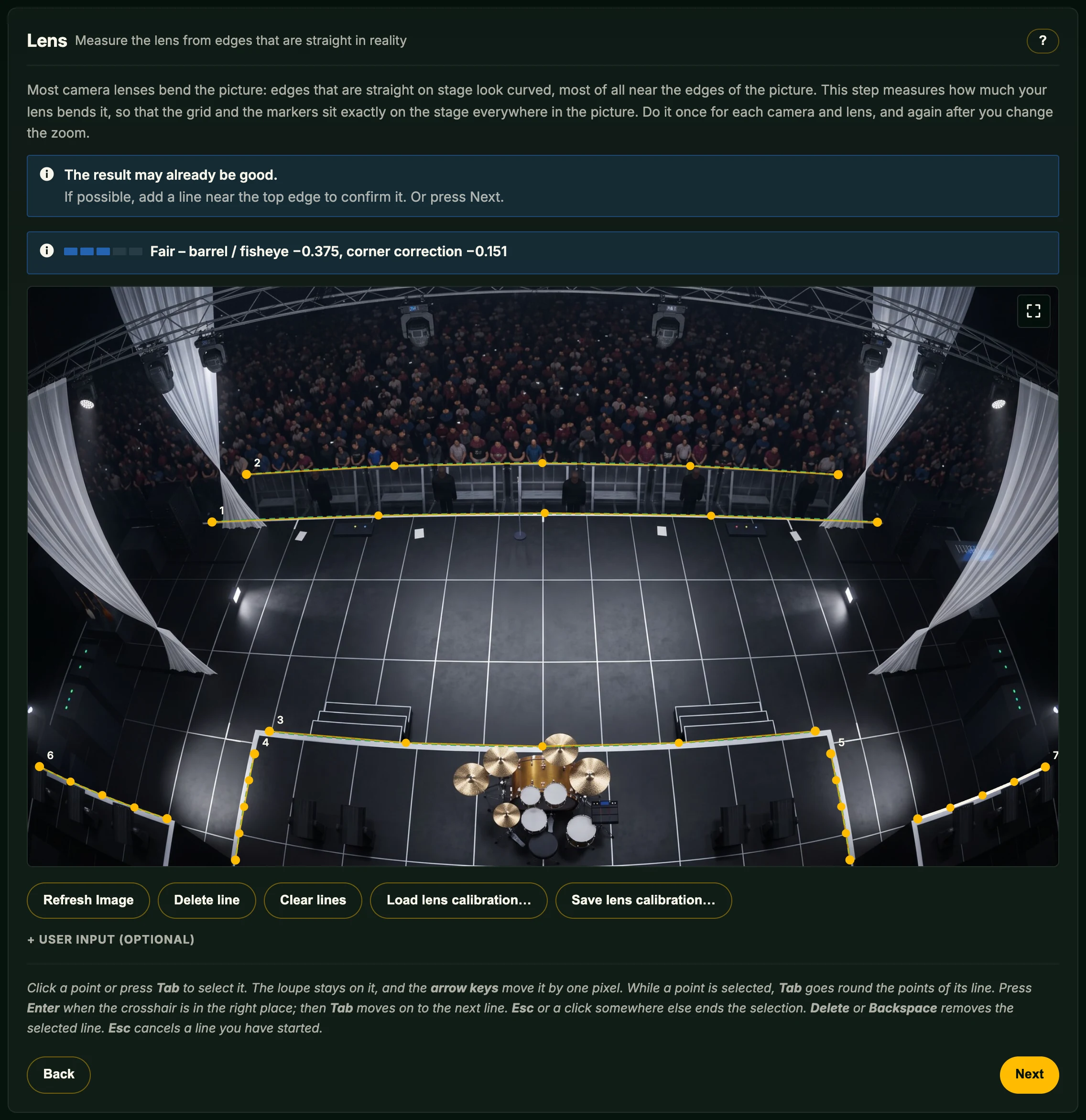
Draw lines on the picture along edges that are straight on stage. Lines near the edges and corners help most. Curtains, cloth and cables are curved; do not use them.
Click the start and the end of a straight edge. The line appears with its middle points on the edge; then move every point exactly onto the edge.
- Click a point or press Tab to select it. The arrow keys move it by 1 px, Shift + arrow by 10 px.
- With a point selected, Tab / Shift+Tab step along the line. Enter ends the selection; then Tab moves to the next line.
- Esc or a click elsewhere ends the selection; Esc also cancels a line you have started.
- Click a line, then Delete or Backspace removes it. Delete line and Clear lines (all lines) are also available as buttons. Refresh Image takes a new snapshot.
With the Experimental feature Lens line suggestions on (General → Station Settings → Advanced Settings → Features), edges show as dashed suggested lines. The check mark in a line's bubble uses it; the cross removes it.
Rating
Five steps show how exactly the lines measure the lens: Not usable, Poor, Fair, Good, Excellent. A Not usable result is shown but not applied, and neither is any result while a line does not fit the others; that line glows in the warning colour and its number is marked !. Without lines reaching toward the corners, Corner correction is an estimate, marked (estimated), and Good or Excellent is shown as Fair.
User input (optional)
- Barrel / fisheye – negative for wide-angle and fisheye images, positive for pincushion.
- Corner correction – extra correction near the corners.
- Right of the picture centre (px) / Above the picture centre (px) – the lens centre. The step does not measure it; type it here or load a calibration that has one.
Load and save
Load lens calibration… takes a calibration saved on this station, an exported .ofsettings file or an OpenCV calibration file (.xml). It must come from the same camera and lens at the same zoom. Loading removes the lines on the picture. A calibration of another picture shape is refused. Save lens calibration… stores the current values under a name; an existing name is replaced.
Camera Calibration
The Calibration option switches between Simple (four corners of a rectangle) and Advanced (known points and triangulated points). Switch units to Imperial / Metric changes the station's unit system, the same setting as in General. In Imperial, type feet and inches (26' 3" or 26 ft 3 in); a number without a unit counts as feet. The stored metric value is shown below each field.
Simple
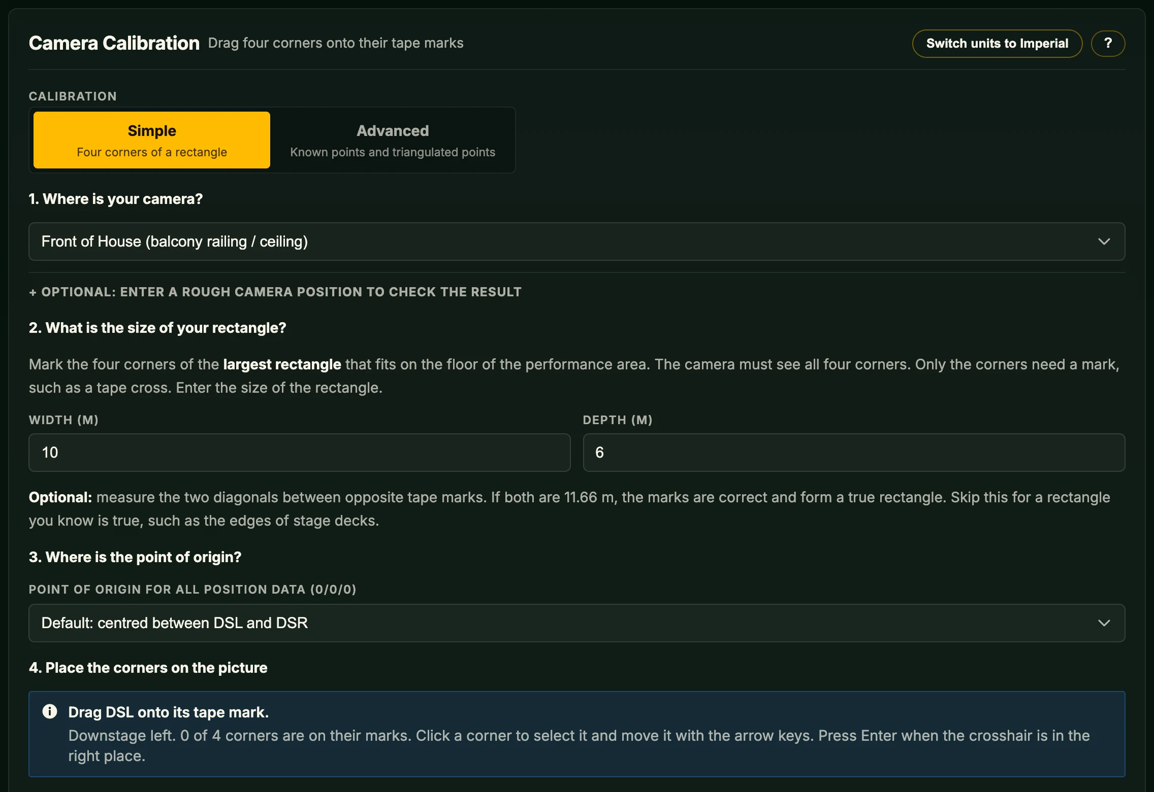
Four steps, each greyed out until the one before it is done.
- 1. Where is your camera? Pick a rough location: Front of House, Front Truss, Back Truss, Stage Left or Stage Right. The drawn rectangle in step 4 is positioned as that camera would see it. Optional: enter a rough camera position to check the result opens Pos X (stage left +), Pos Y (upstage +) and Pos Z (height). It does not change the result; Something might be wrong appears when the calculated camera is further from it than 1 m or a tenth of the camera's distance to the points, whichever is larger.
- 2. What is the size of your rectangle? Mark the four corners of the largest rectangle that fits on the floor of the performance area, with a tape cross at each corner; the camera must see all four. Enter Width and Depth. The wizard shows the expected diagonal. Measure both diagonals on stage – they must match.
- 3. Where is the point of origin? The 0/0/0 point; every position this station sends is measured from it, so it must be the origin of your console or tracking system. Default: centred between DSL and DSR, or Custom: enter the rectangle's centre measured from the origin as X (stage left +), Y (upstage +) and Z (up +).
- 4. Place the corners on the picture. The rectangle is drawn on the picture. Drag each corner (DSL, DSR, USR, USL) onto its tape mark. While you drag, a loupe shows the picture 4× larger. Click a corner or press Tab to select it; the arrow keys move it by 1 px, Tab selects the next corner, Enter places it where it is, Esc or a click elsewhere ends the selection. Reset Corners puts every corner back on the drawn rectangle. Next stays off until all four are placed.
The solved camera and a Corners list appear under the picture. The rectangle's width, depth, centre and height are saved as the grid the Operator Screen draws.
Advanced
Advanced solves the camera from up to 12 points. Of the grid it changes only the height (Floor height on Review).
- Camera Position comes first: Pos X, Pos Y, Pos Z. An estimate within about 2 m per axis is enough; the result is never pulled towards it.
- Known points have an X/Y/Z you type. Two known points far apart, such as DSL and DSR, give about as good a result as four; two close together give a result two to three times worse. A known point outside the picture still counts.
- Triangulated points are found from their distances to two other points plus their height. Two distances allow two places, so a triangulated point must be pinned. Add triangulated point needs two known points. Measure the distances with a laser distance meter (disto): a tape sags and drifts over long distances.
- The calculation needs the camera position, two known points and four pinned points.
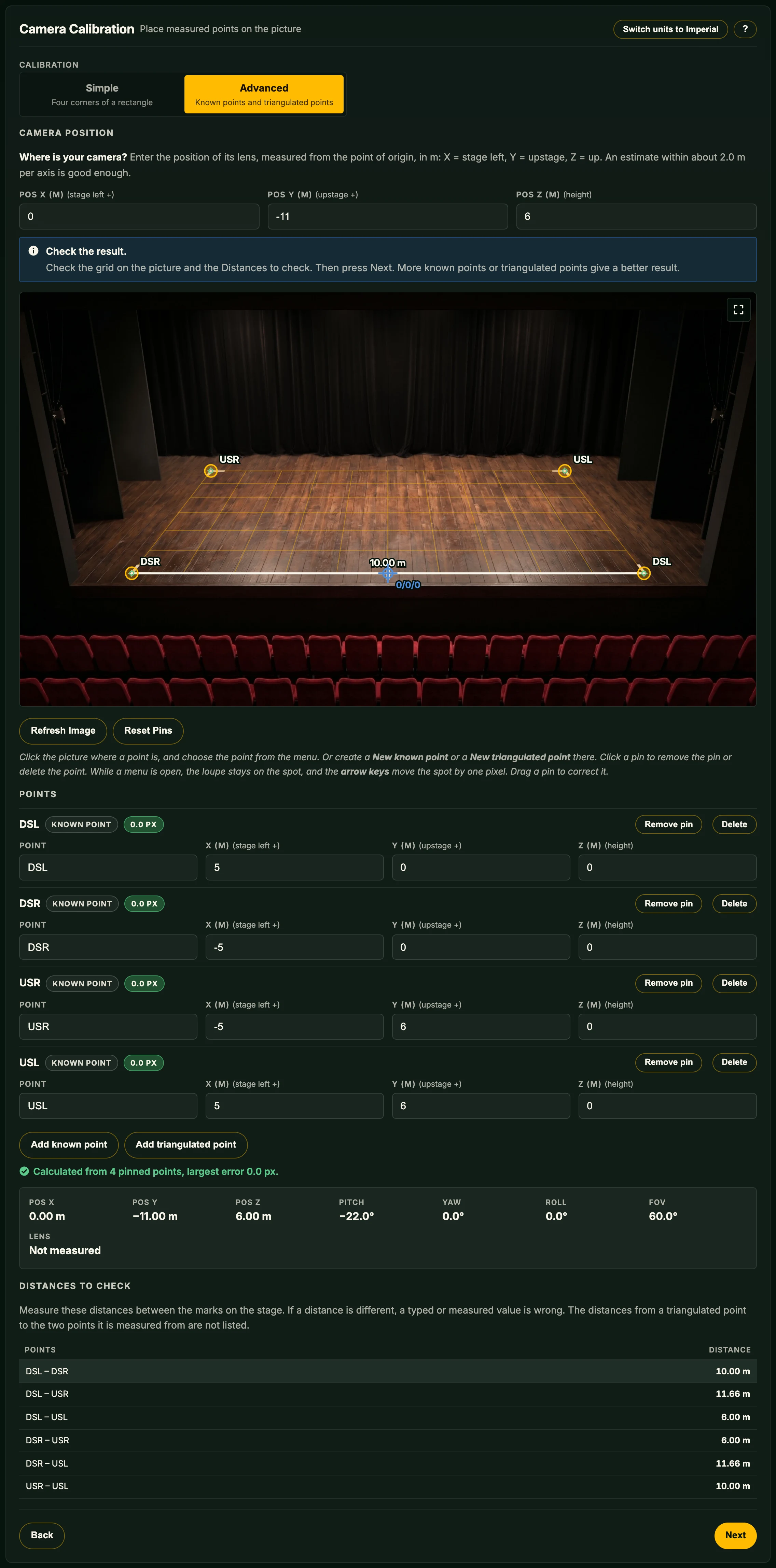
Placing points
Click the picture to open Which point is here? with the points not pinned yet; choose the point at that spot. New known point and New triangulated point turn the menu into fields for a new point; Place point adds it, pinned where you clicked. Click a pin to open its menu: Remove pin keeps the point so you can pin it again, Delete point removes it. The arrow keys move a pin by 1 px, Enter closes the menu, × or Esc closes it without a change. Drag a pin to correct it. Edit every point in the Points list under the picture; Add known point adds one that is outside the picture. Reset Pins removes all pins.
Distances to check
The distances between every pair of points, from the positions you typed and the calculated ones. Measure the same distance between the real marks on stage; if it differs, a value is wrong. They check the shape, not its place – a wrong origin or swapped stage sides give the same distances.
Camera height
From almost straight above, camera height and field of view cannot be told apart. If the camera looks down steeper than −82.5°, a blue box asks for the exact Camera height of the lens, as Z from the point of origin. A missing height is not a warning.
Something might be wrong
Saving is still possible, unless a point is more than 20 px off or behind the camera; then Save and finish stays off. The list covers: a camera far from the entered position, an unusual field of view, a camera below the floor or pointing upwards, and a point that disagrees with the others. Advanced also flags a camera that puts the far floor more than twice as far or as near as the floor points alone do, and a triangulated point whose distances disagree with the picture.
In Simple it also appears when the lens was not measured: nothing was measured, loaded or typed in this run, and the saved Barrel / fisheye and Corner correction are both 0. The corners then look correct, but the calculated camera is wrong.
Switching modes
Switching to Advanced turns the corners into known points and their places on the picture into pins. Switching to Simple clears all points and pins; Simple starts again with the rectangle.
Review
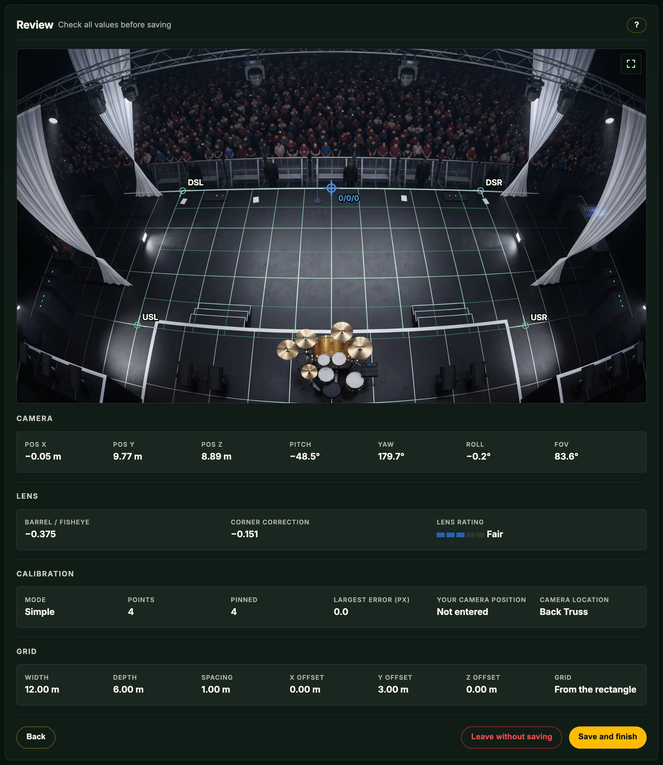
The snapshot shows the solved grid in green – the one the Operator Screen will draw. Below it, read-only groups list the solved camera (position, pitch, yaw, roll, field of view), the lens, the calibration (Points, Pinned) and the grid. Camera height is listed when the camera looks almost straight down or a height was entered. Verify the green grid matches the floor markings, or go Back.
Floor height (Advanced only) is the grid's Z Offset: the floor that a marker's Z line, ground circle and cone are drawn down to, and that a mouse drag moves a marker on. Width, depth and offsets stay as set on the Grid. It starts at the height that most points share, within 5 cm, and the note names those points; otherwise it starts at 0. The green grid follows the value as you type.
- Save and finish saves the camera, the lens and the points; in Simple it also saves the rectangle as the grid. It stays off while a point is incomplete, such as a known point without a value or a triangulated point without a pin; Review names each point and what it needs.
- Leave without saving keeps the station's camera, lens and grid as they were.
- ← Back to Settings returns to the General tab, as do the two buttons above.